Applications
- 2011+ Ford Mustang
- 2011+ Ford F-150
Signal Specifications
While all 2-wire Hall-effect sensors communicate using current-based digital signals, they do not all operate in the same manner. The 2011+ Mustang and 2011–2014 F-150 ABS sensors use a simple switching protocol, whereas the 2015+ F-150 ABS sensors employ a more complex AK communication protocol.
Switching Sensor Protocol (2011+ Mustang, 2011–2014 F-150)
The switching protocol functions similarly to a typical 3-wire Hall-effect sensor. When no tooth is present in front of the sensor, it outputs a low-current logic level of approximately 7 mA. When a tooth passes the sensor, the current rises to 14 mA. The adapter outputs 0 V when the sensor current is 7 mA, and 5 V when the current is 14 mA. The result is a 0–5 V square wave with 50 pulses per wheel revolution and a 50% duty cycle.
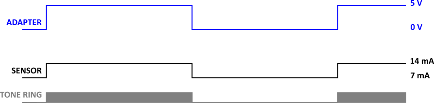
Adapter Output Characteristics:
- Signal Type: 0–5 V or 0–12 V square wave
- Pulse Count: 50 pulses per wheel revolution
- Duty Cycle: 50%
AK Sensor Protocol (2015+ F-150)
The AK protocol allows the sensor to transmit additional information beyond basic wheel-speed data. Each event consists of a high-current (28 mA), 50-microsecond speed pulse, followed by a mid-current (7-14 mA), 9-bit data packet. Once transmission is complete, the sensor enters a 7 mA idle state. Data is transmitted on both the leading and trailing edges of each tooth. The adapter outputs 0 V when the sensor current is 7 mA or 14 mA, and 5 V when the current is 28 mA. The resulting signal is a 0–5 V square wave with 108 pulses per wheel revolution and a fixed 50-microsecond pulse width.

Adapter Output Characteristics:
- Signal Type: 0–5 V or 0–12 V square wave
- Pulse Count: 108 pulses per wheel revolution
- Pulse Width: 50 µs (fixed)
- Timing: Pulses occurs on both the leading and trailing edges of each tooth.
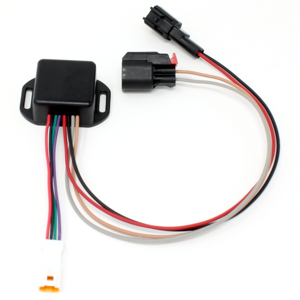
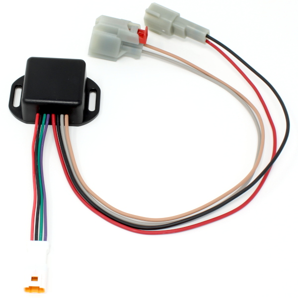
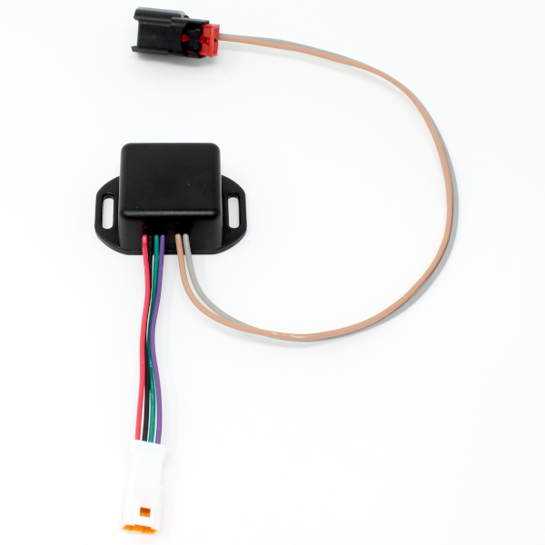
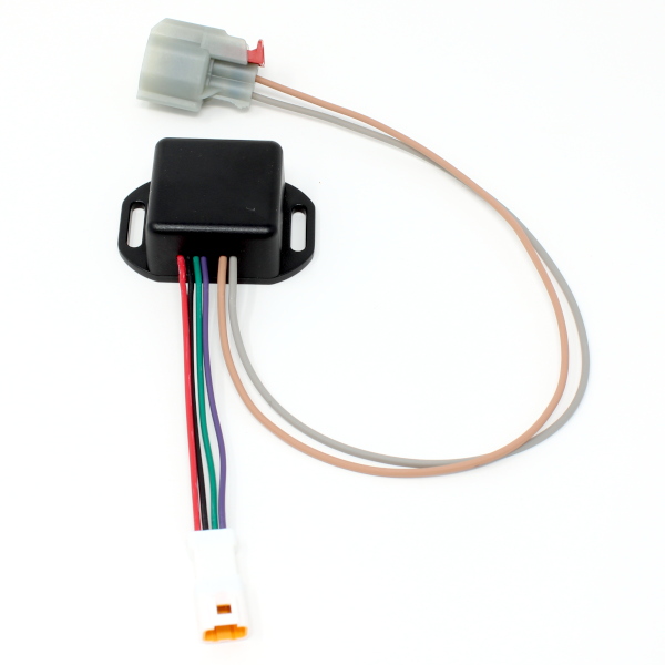
Wire Specifications
| Color | Function |
|---|---|
| Black | Ground |
| Red | Switched/Fused 12 V power |
| Green | Speed Output |