Applications
Converts raw AC signals (VR) or current-based digital signals (MR / 2-wire Hall) into a clean, frequency-matched 0–5 V or 0–10 V square wave.
Supported Sensor Types
Passive VR Sensors: All types (transmission speed, ABS wheel speed, cam/crank position).
Active MR (2-wire Hall) ABS Sensors: Compatible with sensors using the Switching Protocol (see test procedure below).
Technical Specifications
| Feature | Details |
|---|---|
| Supply Voltage | 12–40 V |
| Output Type | 0–5 V, 0–10 V, or Open-Drain |
| Max Input Voltage | ±200 V |
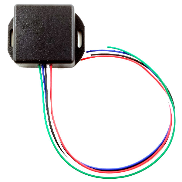
| Dimensions | 2.6″ W × 2.0″ H × 0.8″ D |
| Wire Length | Approx. 12″ (22 AWG) |
Sensor Compatibility Test Procedure
If you are unsure of your sensor type, use a standard multimeter to perform the following steps:
Step 1: VR Sensor Identification
Disconnect the ABS sensor from the module.
Connect multimeter probes to the sensor terminals (polarity irrelevant).
Set your multimeter to AC Voltage and spin the wheel.
Result: If you measure an AC voltage that increases with speed, it is a VR sensor. If you measure nothing, it is a MR sensor—proceed to Step 2.
Step 2: Switching Protocol Test (MR Sensors Only)
With the ABS sensor connected to the module and the ignition in the ‘ON’ position, set your multimeter to DC Voltage.
Identify the Signal Wire: Measure the DC voltage between each ABS sensor wire and ground.
CASE 1: You measure ~11–12 VDC on one wire and 0 VDC on the other. The wire measuring ~11–12 VDC is your signal wire.
CASE 2: You measure ~11–12 VDC on one wire and 0.35–1.5 VDC on the other. The wire measuring 0.35–1.5 VDC is your signal wire.
Test for Protocol: Connect your multimeter to the signal wire identified above and spin the wheel very slowly by hand.
Compatible: If the sensor uses the Switching Protocol, you will see the DC voltage oscillate between two distinct values (e.g., 0.5 VDC and 1.0 VDC) as the tone ring teeth and valleys pass the sensor.
Incompatible: If the voltage on the signal wire remains constant (no oscillation) while the wheel turns, the sensor uses an incompatible communication protocol (such as AK or PSI5).