CORTEX CONFIG 6 – BETA RELEASE NOW AVAILABLE!
Cortex Config 6 brings internal data logging, new boost control strategies, customizable control tables, updated user interfaces, and more to the Cortex EBC!
This is a significant update for the Cortex EBC. When the last update to the Cortex Config software was released in 2019, the Cortex EBC hardware had no remaining memory for additional code. To enable future updates, large parts of the firmware had to be rewritten, and the boost, vehicle, and output configuration files needed to be restructured. As a result, existing configuration files are not compatible with the new version 6 software and firmware.
Page Last Updated: 2/27/2025
WHAT’S NEW IN VERSION 6?
An internal logging feature has been added to allow data recording from the Cortex EBC without needing a laptop in the car. The logger is triggered by boost pressure and automatically stops after collecting 500 data samples, which equals 20 seconds of data at a 25 Hz boost control solenoid frequency. The activation boost threshold can be set to 0.5, 1.0, 1.5, 2.0, or 2.5 PSI.

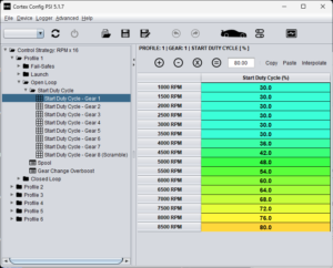
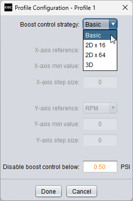
The available boost control strategies have been simplified to four types: Basic, 2D x 16, 2D x 64, and 3D.
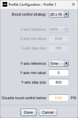
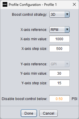
The 2D strategies can be configured to control boost based on RPM, speed, time, or any sensor connected to the general-purpose input. The 3D strategy allows you to use RPM or speed on the x-axis, and the y-axis can reference any sensor connected to the general-purpose input.
The flex-fuel fail-safe, GPI linear fail-safe, and part of the water/methanol fail-safe have been removed and replaced with a new, unified GPI general fail-safe. This new fail-safe can be used with any sensor connected to the general-purpose input. It can be triggered if the sensor’s output falls below a specified value, exceeds a specified value, or falls outside a defined range.
Possible applications for this fail-safe include monitoring AFR, ethanol content, turbo speed, and water/methanol injection pressure or flow.
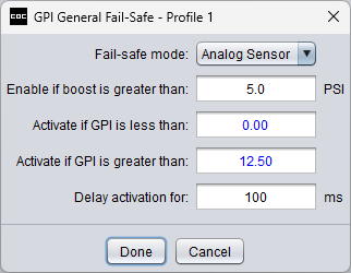
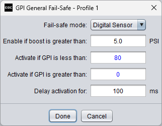
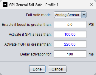
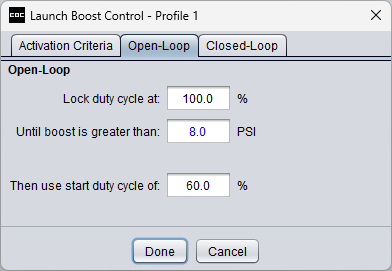
A new “spool” stage has been added to the launch boost control function. This stage allows for a temporarily higher open-loop duty cycle to be used until a sufficient boost level is reached.
The boost scramble control function now has its own dedicated set of control parameters, separate from the individual gear settings.
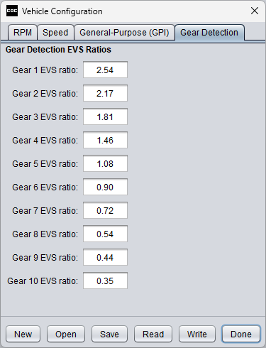
The gear detection now supports up to 10 gears.
The resolution of the EVS (Engine/Vehicle Speed) ratios used for gear detection has been increased from 1.00 to 0.01, which will simplify the gear detection and speed calibration process for many applications.
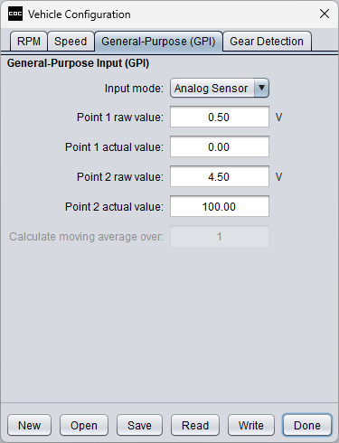
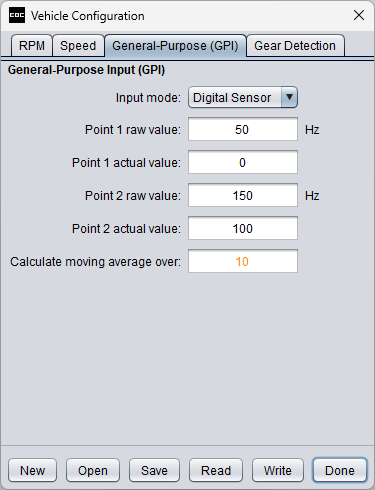
The configuration settings for the general-purpose input have been updated to make the input compatible with a broader range of analog and digital sensors.
3D CONTROL:
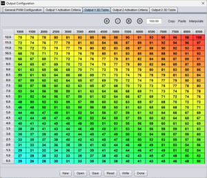
The output control strategy is now completely customizable. Each table axis can be set to reference boost, RPM, speed, or any sensor connected to the general-purpose input.
The scaling of the table axes can be customized by setting the value of the first control point and the spacing between control points.
2D CONTROL:
The output duty cycle ramp can reference boost, RPM, speed, time, or any sensor connected to the general-purpose input.
The ramp rate is now defined by two parameters.
OTHER CHANGES:
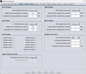
The outputs can now be configured to activate based on any type of sensor connected to the general-purpose input.
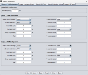
The operation of the outputs is now independent of boost control, and the outputs can now operate when boost control is disabled (profile set to “off).
The available operating modes have been reduced to off and enabled. In the “off” mode, the output is completely disabled. In the “enabled” mode, the output functions according to the settings in the configuration file programmed into the controller.
CONTROLLER:
The controller’s user interface has been revised and the menu system now uses full words that are scrolled across the LED screen.
SOFTWARE:
The parameter names in the software have been updated to make controller configuration more intuitive.
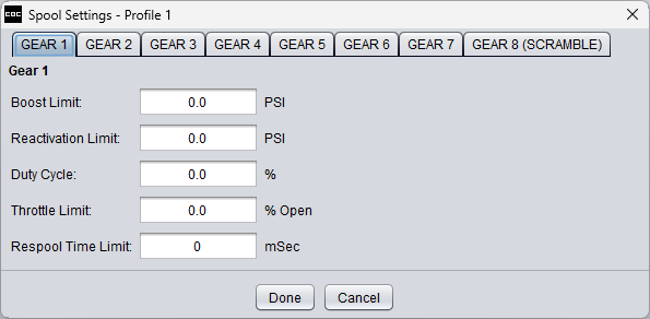
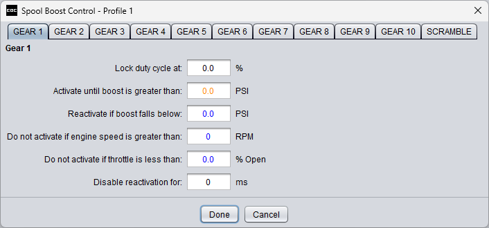
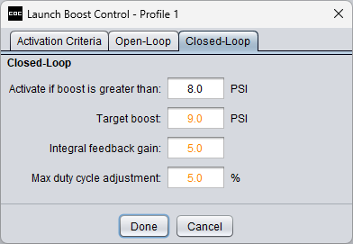
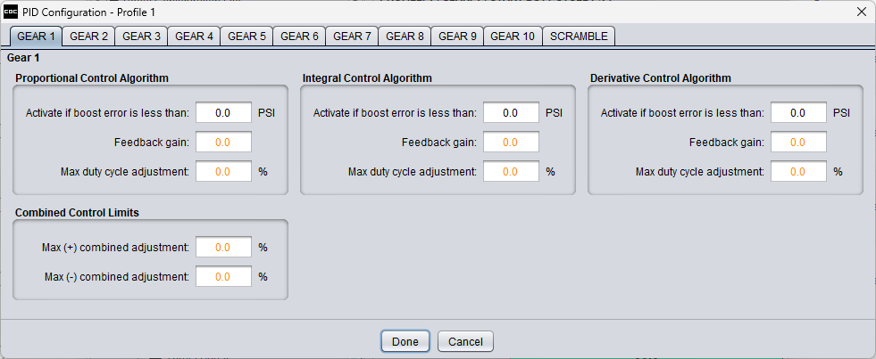
The closed-loop control now adopts standard PID (Proportional, Integral, Derivative) terminology.
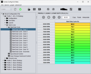
The arrangement of cells on the y-axis of all tables has been reversed, with the highest control point now positioned at the top and the lowest control point at the bottom.
Some parameter text has been color-coded to indicate its significance. Orange text signals that setting the parameter to zero may cause functionality issues. Blue text indicates that the parameter will be entirely ignored if set to zero.
DOWNLOADS
| File | Version | Details | Release Date |
|---|---|---|---|
| Cortex Config 6 Installer | 6.3.3 | Windows (x64 only) | 2/27/2025 |
| Cortex Config 6 Update Instructions | 6.3.3 Rev A | 2/27/2025 | |
| Cortex Config 6 User Manual | 6.3.3 Rev A | 2/27/2025 |

